Contents
- Overview
- Prerequisites
- Bill of Materials
- Supplying Power
- Board Layout
- Rackmount Panel
- TODO
- Revision History
Overview
The ArduinoBoy Advance Rack is an all-in-one rackmount-friendly ArduinoBoy. It builds and improves on some of the ideas of our ShieldBoy to make it more suited for a live environment. Specifically, it is meant to be mounted directly to a 1U panel and uses a DB9 connector for the GameLink connector (though this may be replaced a more up-to-date connection method). It does not require an Arduino Uno baseboard though does still use the same microcontroller and Arduino firmware.
Prerequisites
This is considered a more advanced project and some details have been glossed over, many of which can be found on our ShieldBoy page. It is recommended anyone wishing to build this on their own read that first (and optionally consider building the ShieldBoy first as well).
Bill of Materials
This is still a work in progress so double-check the board/schematics and how you plan on mounting the ABA and make sure you have what you need.
Rack I/O Board
| R1-R6 | 220 Ohm 1/4W Resistor (will vary based on type of LEDs used) |
| R7 | 1k Ohm 1/4W Resistor |
| LED1-LED6 | 3mm LED |
| S1 | 6x6x13mm Tactile Switch |
| IO, GAMELINK | 2×5 DIL Female IDC Connector |
| DB9 | PCB-Mount Male DB9 |
ABA Baseboard
| C1-C2 | 100nF Ceramic Capacitor |
| C3-C4 | 22nF Ceramic Capacitor |
| C5 | 22uF Electrolytic Capacitor |
| R1 | 10k Ohm Metal Film Resistor (1%) |
| R2-R3 | 220 Ohm Metal Film Resistor (1%) |
| R4 | 270 Ohm Metal Film Resistor (1%) |
| R5 | 220 Ohm Metal Film Resistor (1%), Depending on LED Used – Optional |
| PLED | 3mm LED – Optional |
| Q1 | 16MHz 18pF Crystal |
| OK1 | 8-pin Socket (Optional) |
| OK1 | High Speed Photodarlington Optocoupler |
| IC1 | 28-pin Narrow Socket (Optional) |
| IC1 | ATMEGA328P-PU Microcontroller (Same as on Arduino Uno) |
| D1 | 1N4148 Diode |
| IOBOARD, GAMELINK | 2×5 DIL Male IDC Connector |
| GBPWR | 2-pin SIL Header (and Jumper if using +5V from GB) |
| PWR, MIDI-IN | 2-pin SIL Header / MOLEX Locking |
| MIDI OUT | 3-pin SIL Header / MOLEX Locking |
Mounting Hardware
- 6x M3 Male-Female Threaded Hex Standoff (6mm Length)
- 4x M3 Female Threaded Hex Standoff (12mm Length)
- 12x M3 Pan-Head Screw (8mm Length)
- 6x M3 Washer
Game Link Cable
- DB9 Hood with Screws
- DB9 Female Solder Terminal
- Game Link Cable
Supplying Power
To keep the size to a minimum, the ABA requires direct +5VDC power supplied wither by the PWR header, or, optionally power may be supplied from the GameBoy. To use the GameBoy’s power output, be sure you have an appropriately wired GameLink cable and have performed the necessary modifications to the GameBoy itself. Having done that, simply use a jumper on the GB PWR header (and leave the PWR header disconnected). Note that powering the ABA from the GameBoy has never been tested by us as we prefer to use +5VDC directly. If someone has tried this with success, let us know!
Board Layout
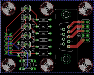
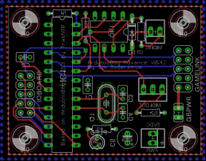
The ABA is actually two boards sandwiched together with the top being used for I/O elements, including the connection to the GameBoy. Though the halves can be held together by their pin headers, we highly recommend using standoff hardware (which is needed to mount the ABA to a panel anyway).
EagleCAD files can be found here. We recommend using OshPark to have the boards fabbed.
Rackmount Panel
Though not absolutely required, the ABA is intended for being mounted behind a 1U panel in a rackmount configuration. Because it is so small, many ABA’s can fit in the same 1U space. Our panel design is not yet finished since we will be using the 1U panel for multiple items (notably extra BPM and step displays from a rackmount MBSEQ). Our current design in Front Panel Express format can be found here and modified to your liking. Though the measurements we have made in the panel seem to fit, we have only implemented a cardboard version of the panel thus far. As a result, it can’t hurt to double-check the measurements before ordering a panel.
Top Board
Bottom Board
TODO
- Replace the DB9 connections with something easier to use and more modern
- Add an audio input, optionally with noise rejection, and balanced output
- Consider an all-in-one non-Rackmount ABA which can be installed in a small hobbyist case
Revision History
ABA Top Board (Rack I/O)
- 1.00 – Initial Fabbed Protoype
ABA Bottom Board
- 0.40 – Initial Fabbed Protoype
- 0.41 – Moved R1, R8, C1 to the other side of the board
- 0.42 – Renamed parts on board/schematic so they are contiguously numbered


